trinityamps.com

Trinity Amps Guitar Amp Forum
It is currently Sat Apr 20, 2024 9:22 am

All times are UTC - 5 hours [ DST ]


Post new topic Reply to topic  [ 2 posts ] 
Author Message
 Post subject: Eyelet wiring technique
PostPosted: Sat Jan 02, 2016 1:57 pm 
Offline
Friend
Friend

Joined: Sat Dec 12, 2015 12:04 pm
Posts: 23
Hi folks,
First build. Still trying to think ahead as much as possible. I have the eyelet board wiring laid out with the jumpers on the bottom and most of the flying leads connecting from the bottom as well. Haven't soldered yet. I've checked the forums for opinions on whether to run the jumpers above or below the board. Cosmetics vs future serviceability I presume. I'm also thinking that running all wires into an eyelet from the same direction would make for better crimping/wire twisting. I'd welcome input on this. What I'm thinking of doing is running jumpers underneath but leaving lots of extra lead (not too much) on top of the board rather than trimming the excess. Thanks in advance for any thoughts people have.


Top
 Profile  
 
PostPosted: Sat Jan 02, 2016 2:53 pm 
Offline
Expert
Expert

Joined: Sat Dec 04, 2010 3:42 pm
Posts: 519
Location: Qualicum Beach, BC
HI George

I would run the jumpers on the bottom of the board. It would be kind of messy to run them on the top. Running the jumpers on the top works if they all line up along the edge of the board. But these would end up running underneath some of the resistors and capacitors if they are on the top. The flying leads can go on the top if you want.

Don't twist or crimp any wires in the eyelets. You want them easily removable if you have to work on the amp in the future. Just run the wires through the eyelets and bend them over a bit on the other side to help hold them in place while you solder. Don't solder an eyelet until all the wires, resistors and capacitors going there are in place. You can trim the excess lead length fairly flush to the board, too.

Pictures of the top and bottom of the board in my Tweed are attached. Note that one eyelet is not yet soldered because that's where the output transformer's center tap wire will attach. You can see how I've bent the leads there over a bit to hold the resistor and capacitor in place and I've also trimmed them fairly flush. That's how the wires are at all the eyelets.

Eyelet board wiring is easier than it seems. You will get the hang of it pretty fast.


Attachments:
BoardTop.jpg
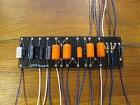
BoardTop.jpg [ 299.39 KiB | Viewed 4996 times ]
BoardBottom.jpg
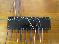
BoardBottom.jpg [ 287.5 KiB | Viewed 4996 times ]
Top
 Profile  
 
Display posts from previous:  Sort by  
Post new topic Reply to topic  [ 2 posts ] 

All times are UTC - 5 hours [ DST ]


Who is online

Users browsing this forum: No registered users and 9 guests


You cannot post new topics in this forum
You cannot reply to topics in this forum
You cannot edit your posts in this forum
You cannot delete your posts in this forum
You cannot post attachments in this forum

Search for:
Jump to:  
cron
Powered by phpBB® Forum Software © phpBB Group