trinityamps.com

Trinity Amps Guitar Amp Forum
It is currently Wed Apr 24, 2024 3:23 pm

All times are UTC - 5 hours [ DST ]


Post new topic Reply to topic  [ 26 posts ]  Go to page Previous  1, 2
Author Message
PostPosted: Mon Sep 18, 2017 7:25 pm 
Offline
Novice
Novice

Joined: Fri Oct 26, 2012 8:51 pm
Posts: 108
Here is the rest of the Turret Board installation. I already installed the flying leads; so you will see glimpses of them.

Phase inverter components part 1
Attachment:
DSCN2900 - Copy  (1).JPG
DSCN2900 - Copy (1).JPG [ 176.7 KiB | Viewed 4811 times ]


Phase inverter components part 2
Attachment:
DSCN2900 - Copy  (2).JPG
DSCN2900 - Copy (2).JPG [ 113.91 KiB | Viewed 4811 times ]


TMB area components
Attachment:
DSCN2900 - Copy  (3).JPG
DSCN2900 - Copy (3).JPG [ 155.99 KiB | Viewed 4811 times ]


Preamp (V1 area) components
Attachment:
DSCN2900 - Copy  (4).JPG
DSCN2900 - Copy (4).JPG [ 127.12 KiB | Viewed 4811 times ]


Input side of V1 area components
Attachment:
DSCN2900 - Copy  (5).JPG
DSCN2900 - Copy (5).JPG [ 106.04 KiB | Viewed 4811 times ]


Full picture of completed Turret Board components. Also, I used a thicker 20 gauge wire for the ground buss.
Attachment:
DSCN2900 - Copy .JPG
DSCN2900 - Copy .JPG [ 578.21 KiB | Viewed 4811 times ]


C2


Top
 Profile  
 
PostPosted: Mon Sep 18, 2017 10:58 pm 
Offline
Expert
Expert

Joined: Sat Dec 04, 2010 3:42 pm
Posts: 519
Location: Qualicum Beach, BC
Looks good! Keep up the great work, you are almost done!


Top
 Profile  
 
PostPosted: Tue Sep 26, 2017 11:34 pm 
Offline
Novice
Novice

Joined: Fri Oct 26, 2012 8:51 pm
Posts: 108
Here are pics of the tube socket wirings. First the preamp and power inverters (V1, V2, V3)

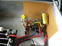
Here is V1. Notice that I used the four-tag terminals to make it easier to install the VRM coupling capacitors [and for the cascade mod that I will be installing (cascading TMB into Normal channel)]. I have not connected any wiring form the normal channel's coupling capacitor to pin 7 because that will take place with the cascade mod wiring later.
Attachment:
V1a.JPG
V1a.JPG [ 413.64 KiB | Viewed 4787 times ]

Attachment:
V1c.JPG
V1c.JPG [ 1.73 MiB | Viewed 4787 times ]


Here is V2
Attachment:
V2.JPG
V2.JPG [ 498.55 KiB | Viewed 4787 times ]


Here is V1 and V2
Attachment:
V1 V2b.JPG
V1 V2b.JPG [ 791 KiB | Viewed 4787 times ]
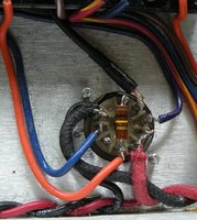

Here is V3
Attachment:
V3.JPG
V3.JPG [ 316.32 KiB | Viewed 4787 times ]


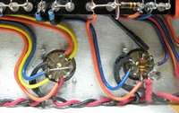
Here is V2 and V3. I ran the boost wire (dark blueish purple) from V2 pin 3 to the 2k7 resistor, and then on to the DPDT push-pull potentiometer switch that I installed on the TMB Gain Pot. Then ran the boost wire (light blue) from the switch back to the other 2k7 resistor on the turret board. I double checked it several times to make sure that the second resistor was engaging with the push-pull switch. It works.
Attachment:
V2 V3.JPG
V2 V3.JPG [ 926.71 KiB | Viewed 4787 times ]


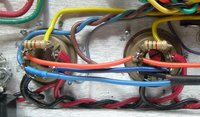
Here are V4 and V5 (the EL84 power amp tubes)
Attachment:
V4-V5.JPG
V4-V5.JPG [ 974.15 KiB | Viewed 4787 times ]


Here are V6 and V7 (the 6V6 power amp tubes)
Attachment:
V6-V7.JPG
V6-V7.JPG [ 532.12 KiB | Viewed 4787 times ]


Here is a picture of most of the tubes.
Attachment:
tubes.JPG
tubes.JPG [ 623.65 KiB | Viewed 4787 times ]


You may notice the small gray and purple cathode wires. I used 600v wire to go to the cathode switch which is a push-pull dpdt 500k potentiometer installed for the Bass pot. The cathode switch wires run from the power tubes under the board and to the potentiometer switch, then back to the turret board. I will post pics of the potentiometer side later.

Also, please excuse the cat hair in some of the pictures; it gets on everything. I have since cleaned all the sockets with alcohol and removed the dust and hair.

C2


Top
 Profile  
 
PostPosted: Wed Sep 27, 2017 9:08 am 
Offline
Holy Ghost
Holy Ghost
User avatar

Joined: Sun Mar 13, 2005 4:10 pm
Posts: 7519
Location: Canada
Looking good so far! Neatly done!

_________________
Stephen
Web: www.trinityamps.com. Facebook: facebook.com/trinityamps. Twitter: @trinityamps


Top
 Profile  
 
PostPosted: Sun Oct 15, 2017 5:14 pm 
Offline
Novice
Novice

Joined: Fri Oct 26, 2012 8:51 pm
Posts: 108
It has been a while, but I made some progress. Here are pictures of the cathode switch. FYI--I put it on a 500k Push-Pull Potentiometer and used this for the Bass Potentiomenter. I ran the wires (small gray and small purple) from the cathodes on the EL84 (pin three) and 6V6 (pin eight) tubes under the turret board and up to the push-pull switch, and then back to the 150R and 250R resistors on the turret board. I twisted all of these wires and heat-shrink wrapped them. I double checked to make sure that the switch was engaging the correct sides. Also, I chose to wire the cathode switch so that the 6V6 side is the default (pushed-in side), and the EL84 side is engaged by pulling the push-pull switch.

First, here is the overview picture. It shows the three potentiometers (now wired), and the cathode switch (sorry for the blurry focus of the switch). I decided to use different color wires (orange, blue and yellow) for the middle and treble potentiometers leads that went directly to the turret board; this just makes it easier for me to keep them organized.
Attachment:
Cathode Bass Middle Treble pots.JPG
Cathode Bass Middle Treble pots.JPG [ 1.72 MiB | Viewed 4697 times ]


Second, here is a closeup of the cathode switch showing both sides of the switch and the two 220k resistors.
Attachment:
cathode switch push pull close up.JPG
cathode switch push pull close up.JPG [ 294.42 KiB | Viewed 4697 times ]


Third, here is an picture from a little higher up showing the switch and the gray & blue wires twisted and running under the turret board.
Attachment:
Cathode switch.JPG
Cathode switch.JPG [ 988.5 KiB | Viewed 4697 times ]


Next to come will be the wiring of the boost switch.
C2


Top
 Profile  
 
PostPosted: Mon Oct 16, 2017 8:44 pm 
Offline
Holy Ghost
Holy Ghost
User avatar

Joined: Sun Mar 13, 2005 4:10 pm
Posts: 7519
Location: Canada
Thanks for the update. Looks nice.

_________________
Stephen
Web: www.trinityamps.com. Facebook: facebook.com/trinityamps. Twitter: @trinityamps


Top
 Profile  
 
Display posts from previous:  Sort by  
Post new topic Reply to topic  [ 26 posts ]  Go to page Previous  1, 2

All times are UTC - 5 hours [ DST ]


Who is online

Users browsing this forum: No registered users and 12 guests


You cannot post new topics in this forum
You cannot reply to topics in this forum
You cannot edit your posts in this forum
You cannot delete your posts in this forum
You cannot post attachments in this forum

Search for:
Jump to:  
Powered by phpBB® Forum Software © phpBB Group