|
Greetings folks
First off, what an incredible sounding amp! Just amazing harmonic grind and note definition. I now completely understand what all the fuss is about with regards to the 18Watt circuit. Thanks Steven for putting together such a fantastic kit. When I first plugged in it made me instantly realize that my previous single ended build was a muddy piece of .... you know.
Anyway, when I first sparked up the plexi some time ago I had no problems with channel 1. However, the signal wasn't getting through channel 2 (TMB). I was able to trace it to the input with the "pop" test, and subsequently removed the dual cliff jacks and replaced it with a single jack I had laying around and paralleled the 68K resistors to reflect 34K at the input to simulate the high input (I assume I have this correct?). After making this change it worked straight away. A bit more gain than I expected .. not complaining at all .. but I guess this may have something to do with active pickups in my SG.
When I looked at the dual jack set-up I couldn't see anything obvious that I had done wrong. It looked the same and appeared to behave the same as channel 1 with regards to continuity with and without jacks plugged in. When installed it produced a lot of hum from the hi input with no signal getting through but had a very quiet response in the low input with just a whisper of signal getting through. So I have been using it with a single input for some time but would like to put it back to the dual inputs so that it’s set-up as intended. The question I have is this. Is there any type of testing that can be done to the assembled jacks on the bench to confirm it is operating properly before I install it? I find it hard to work on it once it’s in-place in the chassis. Also, I get a bit confused by the operation of the dual jack concept.
| Attachments: |
File comment: Inputs
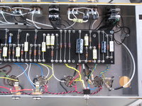
IMG_5447.JPG [ 1.07 MiB | Viewed 6689 times ]
|
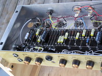
IMG_5446.JPG [ 1023.79 KiB | Viewed 6689 times ]
|
|


