trinityamps.com

Trinity Amps Guitar Amp Forum
It is currently Sun Jun 16, 2024 1:59 am

All times are UTC - 5 hours [ DST ]


Post new topic Reply to topic  [ 15 posts ] 
Author Message
PostPosted: Sun Jun 12, 2016 11:02 am 
Offline

Joined: Wed Jun 01, 2016 7:54 am
Posts: 8
Hey guys, just joined up as this is my first time building an amp (though I've done plenty of similar work) and figured I should go straight to the source with any questions. Let me just say I'm thrilled with my choice of kits, the quality of parts and service so far with Trinity is amazing and I can already see how amp building becomes addicting. :D

I have begun assembly on my 18W and wanted to run a few things by you guys as I progress. I have the turret board assembled already but wanted to be sure I wired the heater wires up correctly before I proceed, and I'm a little unsure of wiring the transformers so I may have a follow up question later this evening as I tackle it.

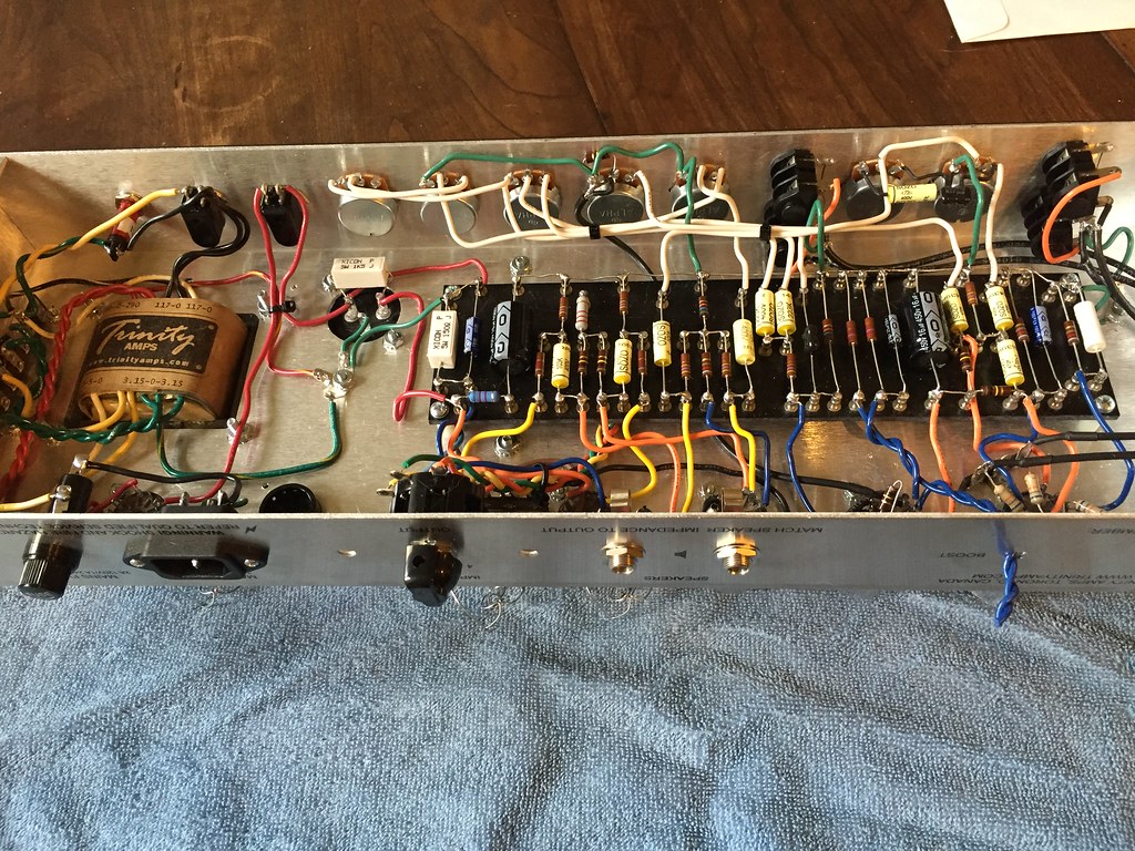
Anyway, first off I have 5 lugs on my terminal strip as opposed to the 4 on the wiring diagram posted with the instructions, I assume this is not an issue as long as you connect all the various components together but just wanted to make sure I didn't screw anything up. It bolts in place properly so I'm assuming its as it should be, but again, just wanted to make sure.
Image

And then just a general question, should I try to wrap these up a little better, or are they OK like this? Its obviously a little tricky to balance neatness with needing to reach the proper pins on the tube sockets.
Image

Finally a two-part question, a) when I soldered this in place the plastic sheathing on the wire melted away a bit, should I either unsolder this and put some heat shrink on it, or just wrap it in some electrical tape? b) how close should I cut the ends of the wire to the pins on the tube sockets? I obviously don't want anything touching in there but wasn't sure how tight it needs to be.
Image

That should be it for now, but I'm sure I will have more stupid questions for you guys! :P


Top
 Profile  
 
PostPosted: Sun Jun 12, 2016 2:46 pm 
Offline
Expert
Expert

Joined: Sat Dec 04, 2010 3:42 pm
Posts: 519
Location: Qualicum Beach, BC
Hi, welcome to the forum!

The only stupid questions are the ones you don't ask.

Your heater wiring looks good. It doesn't have to be wound any tighter at the tube sockets, unless you are going for super neatness!

You should remove that melted heater wire from the socket and put some heat shrink tubing on it. Electrical tape tends to not work well when there is a tight bend like that. It's tricky some times to get the right amount of heat on a joint without melting the insulation on the wire.

Trim your wires flush to the solder joints. You don't have to leave them sticking out.

The five lug terminal strip is fine. From the layout drawing it looks like you only have to use four of them, though. You can leave the fifth one as it is or fold down.


Top
 Profile  
 
PostPosted: Sun Jun 12, 2016 9:56 pm 
Offline

Joined: Wed Jun 01, 2016 7:54 am
Posts: 8
mitch m wrote:
Hi, welcome to the forum!

The only stupid questions are the ones you don't ask.

Your heater wiring looks good. It doesn't have to be wound any tighter at the tube sockets, unless you are going for super neatness!

You should remove that melted heater wire from the socket and put some heat shrink tubing on it. Electrical tape tends to not work well when there is a tight bend like that. It's tricky some times to get the right amount of heat on a joint without melting the insulation on the wire.

Trim your wires flush to the solder joints. You don't have to leave them sticking out.

The five lug terminal strip is fine. From the layout drawing it looks like you only have to use four of them, though. You can leave the fifth one as it is or fold down.
Thanks for the help!

Good point about the electrical tape, I redid it with some heat shrink and cut all the wires nice and short. Now a few more questions about the transformer wiring...

1. The black/red and black wires are flipped on my transformer compared with the diagram. Again, I figure as long as I follow the connections according to the diagram I should be OK but figured I'd see if something was up.
Image

2. I seem to be a missing a few KEPS nuts, or I used them in the wrong places, anything wrong with using regular nylon nuts if I can't find any replacements locally?

3. I see mention of the blue/white brown/white wires on the output transformer not being used on the 18W builds and to just tuck them away. Mine didn't seem to have any to begin with, has there been an update to the transformer that gets rid of these for these kits?

4. I went ahead and cleaned up the wiring I've done so far with some cable ties, is there any reason I should not have the wires so close to each other? I figured it would look nice but can easily get rid of it if it will lead to hum, etc...
Image

These are probably pretty obvious questions but just figured I may as well ask so I don't have to go back and fix anything down the road...


Top
 Profile  
 
PostPosted: Mon Jun 13, 2016 1:03 am 
Offline
Expert
Expert

Joined: Sat Dec 04, 2010 3:42 pm
Posts: 519
Location: Qualicum Beach, BC
Transformer construction can vary. The wire colors are always the same, though. As long as you connect the black and black/red wires to the power switch as shown in the schematic you will be right.

Black/white and white go to the neutral lug on the IEC power connector.

Stephen can probably verify this, but I guess the output transformers changed to eliminate the blue/white and brown/white primary wires that aren't used in 18 watt amps. If yours doesn't have them you don't have to worry.

Don't worry too much about the keps nuts, either. If you can get some, or lock washers, go ahead and use them. Otherwise just get the nuts tight and move on.

As for bundling wires, don't bundle heater wires and high voltage wires together. It's not good wiring practice to bundle high voltage wires with low voltage ones.

Generally just bundle the stranded wires on the transformers. You can twist or bundle each group of similar wires, but don't bundle the groups together.

When you get to the signal wires, they shouldn't need bundling. Just keep them as far away as you can from high voltage (AC or DC) and the heater wires.


Top
 Profile  
 
PostPosted: Mon Jun 13, 2016 11:38 am 
Offline

Joined: Wed Jun 01, 2016 7:54 am
Posts: 8
Great, thanks again for all the help!


Top
 Profile  
 
PostPosted: Mon Jun 13, 2016 7:19 pm 
Offline

Joined: Wed Jun 01, 2016 7:54 am
Posts: 8
Alright time for my daily stupid question!

What should I use for the main power wires? It doesn't seem like there were any wires designated for it, and I feel like I shouldn't use the smaller 22 awg stuff that the rest of the components use. I also don't think I have a long enough piece of cutoffs from the transformers to use.

I'm gonna try one more local place tomorrow but Home Depot didn't have any solid wire that was rated for high voltage in anything under 14 awg and I certainly didn't want to try twisting that stuff :lol:


Top
 Profile  
 
PostPosted: Tue Jun 14, 2016 12:17 am 
Offline
Expert
Expert

Joined: Sat Dec 04, 2010 3:42 pm
Posts: 519
Location: Qualicum Beach, BC
Use 18 awg wire for the power. Stranded wire is OK. There should have been some with the kit. But you should be able to get some at Home Depot, even if it's part of two-conductor lamp cord, an IEC cable or something similar. 16 awg is OK too.

You can bundle these wires with cable ties or twist them together.


Top
 Profile  
 
PostPosted: Tue Jun 14, 2016 1:57 pm 
Offline

Joined: Wed Jun 01, 2016 7:54 am
Posts: 8
Welp I drove to all the local wire supply shops in town today over lunch and none of them had what I was looking for, I picked up the 14 awg solid core from Home Depot to have something. I figure too big is better than too small, I assume this stuff should be OK to use?


Top
 Profile  
 
PostPosted: Tue Jun 14, 2016 10:29 pm 
Offline
Expert
Expert

Joined: Sat Dec 04, 2010 3:42 pm
Posts: 519
Location: Qualicum Beach, BC
Well, it will work although it's way bigger than you need. It might be kind of hard to work with but it will definitely stay where you put it!


Top
 Profile  
 
PostPosted: Thu Jun 16, 2016 9:01 pm 
Offline

Joined: Wed Jun 01, 2016 7:54 am
Posts: 8
So I realized I made a few stupid wiring mistakes, but I'm pretty sure I got them corrected (though given the results I know something is still wrong :oops: ). I also abandoned the Home Depot wires and used some transformer cutoffs for the main wires and they seem to be doing fine.
Image

Anyway, my issue now is I have no sound coming out at all from the input jacks. If I tap some of the tube pins I can get a sound out of the speaker so its definitely capable of producing sound, just not from where I want. I know this is near impossible to do without seeing the amp in person but does anyone have any ideas on where I should start checking for a bad connection? Checking with my multimeter all the jacks seemed wired correctly and when a cable is plugged in I can trace the signal until I hit the resistors on the terminal strip. Past that I'm afraid I can't be sure where the fault is.

I feel like I've triple checked all the wiring at this point but something is clearly still amiss so any suggestions would be great appreciated! :thumbsup:


*EDIT* Oh I also forgot to mention that I broke the mini boost switch by over tightening it (and USPS has now lost the replacement) could that be in any way involved in my problems? I've tried combinations of the two wires connected and not connected to no avail.


Top
 Profile  
 
PostPosted: Thu Jun 16, 2016 11:38 pm 
Offline
Expert
Expert

Joined: Sat Dec 04, 2010 3:42 pm
Posts: 519
Location: Qualicum Beach, BC
The Boost switch not being there won't cause problems. You just won't get any boost without it unless you short together the wires leading to the switch.

The first thing to do when troubleshooting a new build is check visually to make sure all the wiring is correct. Sounds like you have already done that.

Then check the voltages to see if they are relatively close to what is shown on the schematic. If anything is way off, your problem is in that area.

If all the wiring looks good, check with an ohm meter to make sure everything that is supposed to be conncted actually is. Do this following the layout drawing or the schematic, with the amp off, and the capacitors fully discharged. Measure from the leads on the components rather than the solder connections. The readings should be close to 0 ohms.

Also check for anything accidentally shorting to ground, especially with the shielded cables.

Do you hear a bit of hum or hiss coming out of the speaker? That would be good and it means the power amp section is probably working.


Top
 Profile  
 
PostPosted: Fri Jun 17, 2016 10:01 am 
Offline

Joined: Wed Jun 01, 2016 7:54 am
Posts: 8
Success!

I must have been confused in the beginning by what was meant by daisy-chaining the heater wires as I was getting wrong voltages in the 12AX7's, but I fixed those up and now they are operating correctly and I have glorious sound! At least from the Normal channel, the TMB channel is acting funny as it is very faint to nonexistent unless I have the pots completely off but I'm hoping that is just a matter of something in the pot's wiring being grounded that shouldn't be. Hopefully I can figure that out tonight when I get home...

Thanks again Mitch for all the help!


Top
 Profile  
 
PostPosted: Sat Jun 18, 2016 2:13 pm 
Offline
Expert
Expert

Joined: Sat Dec 04, 2010 3:42 pm
Posts: 519
Location: Qualicum Beach, BC
Glad you got the Normal channel fixed.

Check the shielded cable going to the Gain pot on the TMB channel, too. There could be a short to ground there.


Top
 Profile  
 
PostPosted: Sat Jun 18, 2016 7:57 pm 
Offline

Joined: Wed Jun 01, 2016 7:54 am
Posts: 8
Alright I've redone all the shielded cables, and the ground wire on the turret board to no avail, still really reduced output on the TMB channel.

Here are the voltages I measured today, with the tubes installed, a few of them seemed a bit out of place but I'm not sure how precise tubes usually operate:

V1
1: 155
3: 1
6: 141
8: 1

V2
1: 249
3: 1.95
6: 249
8: 176

V3
1: 182
2:32
3: 72
6: 186
7: 32
8: 172

V4
3: 12
7: 343
9: 331

V5
3: 12
7: 343
9: 331

V5
1: 309
3: 357
7: 309

As I said a few seem a bit higher, and others a bit lower, than what is called for but I'm not sure what the standard deviation with this sort of thing usually is. The only things that really stuck out to me were Pin 1 of V2 was 249 instead of 180 and Pin 1 of V3 was 182 instead of 220 but I have no clue what that would tell me. V3 also had low voltage (Pin 2: 32 instead of 52 and Pin 7: 32 instead of 62) but everything else seemed to be at least close to what it should be.

Other than that I'm sort of lost as to what else to check, I've reflowed most of the solder joints and checked for continuity at most if not all the connections and I'm still not really coming up with anything that could tell me where the issue is. I think soon I may have to throw in the towel and take it to a local amp shop and see if they can look it over.


Top
 Profile  
 
PostPosted: Sun Jun 19, 2016 12:35 am 
Offline
Expert
Expert

Joined: Sat Dec 04, 2010 3:42 pm
Posts: 519
Location: Qualicum Beach, BC
Check R7. Make sure it measures 100K and nothing is shorting it. Also verify that it runs from pin 1 to pin 6 of V2 and there is a jumper running from pin 1 to pin 7. You show the voltage being the same at pins 1 and 6 of V2 and they should be different.

If R7 is OK can you swap in a different tube for V2? Also really make sure all your wiring to V2 is good, and V2's socket itself is good too.

The rest of the voltages seem reasonable. The V3 voltages are somewhat lower than what's shown on the schematic. They are about the same on both halves, though, which is what matters there. And you said the Normal channel works fine so V3 and the two output tubes are working properly.


Top
 Profile  
 
Display posts from previous:  Sort by  
Post new topic Reply to topic  [ 15 posts ] 

All times are UTC - 5 hours [ DST ]


Who is online

Users browsing this forum: No registered users and 26 guests


You cannot post new topics in this forum
You cannot reply to topics in this forum
You cannot edit your posts in this forum
You cannot delete your posts in this forum
You cannot post attachments in this forum

Search for:
Jump to:  
Powered by phpBB® Forum Software © phpBB Group