trinityamps.com

Trinity Amps Guitar Amp Forum
It is currently Thu Apr 25, 2024 4:20 am

All times are UTC - 5 hours [ DST ]


Post new topic Reply to topic  [ 21 posts ]  Go to page 1, 2  Next
Author Message
PostPosted: Wed Dec 25, 2013 10:11 am 
Offline
Friend
Friend

Joined: Wed Dec 25, 2013 9:15 am
Posts: 14
Location: Santa Cruz, CA
Starting my first amp build. I currently have and play through a 59 Bassman reissue, a Blues Junior, and an Egnater Rebel 20, so you can probably tell I like that Fender tone. So much so that if this amp works out, I'm likely to sell the Egnater (have never quite grown to like it as much as I expected) and replace it with the 5E3.

I've done lots of guitar wiring, including on-board active electronics and effects and even a pickup mixer (back in the 80s), and have done some limited stomp box wiring, but this is my first time working with tubes. I've never been a great solderer, but managed to get by. Fortunately, my son, fresh out of high school electronics electives, is a great solderer, and he's helping me out with this build.

I ordered a kit and cab from Stephen, and he sent it out once the cab was complete. After a shipping-related hiccup that resulted in a bent chassis, Stephen rushed me out a replacement just in time for xmas!

Some quick pics, and then some notes about my concerns/questions so far...

Front hardware:
Attachment:
File comment: Front hardware
photo 2.JPG
photo 2.JPG [ 2.4 MiB | Viewed 22061 times ]


Back hardware:
Attachment:
File comment: Back hardware
photo 1.JPG
photo 1.JPG [ 2.32 MiB | Viewed 22061 times ]


Top
 Profile  
 
 Post subject: Heater wiring...
PostPosted: Wed Dec 25, 2013 10:19 am 
Offline
Friend
Friend

Joined: Wed Dec 25, 2013 9:15 am
Posts: 14
Location: Santa Cruz, CA
Here are some pics for the heater wiring. We actually started from the "end" at V1 and traced in to the lamp, which seems to be opposite the recommended approach in the manual (seems like it wanted us to start at the lamp and go out from there to the power tube sockets, and thence to the preamps), but I figured it might be easier going the other direction. I know, second-guessing the docs is probably not a good first step, we'll see...

Starting with the preamp sockets:
Attachment:
File comment: Preamp tube heaters
photo 5.JPG
photo 5.JPG [ 2.17 MiB | Viewed 22060 times ]


Working backwards through the power tubes:
Attachment:
File comment: Power amp tube heaters
photo 4.JPG
photo 4.JPG [ 1.74 MiB | Viewed 22060 times ]


And finally up to the lamp:
Attachment:
File comment: Heaters to lamp
photo 3.JPG
photo 3.JPG [ 2.14 MiB | Viewed 22060 times ]


I ran the twisted heater wires along the inside edge of the chassis, is that right? Wasn't sure where to put the run from the power tube sockets to the lamp, so I just let it hang in free space; worried that it will become a PITA to work around it later. Should I be running it along the front of the chassis (next to where the transformers will go)?


Top
 Profile  
 
 Post subject: Slippy Pot Stems...
PostPosted: Wed Dec 25, 2013 10:28 am 
Offline
Friend
Friend

Joined: Wed Dec 25, 2013 9:15 am
Posts: 14
Location: Santa Cruz, CA
Another gotcha I discovered when installing the fuse: the fuse housing had broken during shipping, and I hadn't noticed until now. When I did my BOM check, I only glanced at the contents of that bag without taking everything out. Consequently, I had to go out on xmas eve on a quest to find any store that was open and had a 2A 250V fuse. I found a local guitar store, 15 minutes before they closed; woo-hoo!

The only other issue I ran into was that the pot shafts are very slippery, and I'm finding it near impossible to get the chicken head knobs to keep firmly in position. I've tightened down the set screws (one of the chicken heads had a _very_ stiff set screw!!! the other two were fine), but the knobs still turn past the stopping point, when given a bit of pressure. Perhaps I'll take a dremel to the shaft and try to score a hole or flattened area that the set screw and dig into, but before I do, has anyone else solved this problem?

I'm used to the pot shafts that have a flat side, which allows the set screw to sit on the flat side, from whence it cannot move.


Top
 Profile  
 
PostPosted: Wed Dec 25, 2013 1:42 pm 
Offline
Expert
Expert

Joined: Sat Dec 04, 2010 3:42 pm
Posts: 519
Location: Qualicum Beach, BC
Hello and Merry Christmas!

Your wiring looks really neat so far. Yes, you should tuck the heater wiring under the lip of the chassis. One thing I can suggest is you keep the heater wires close to the chassis all the way to the tube sockets rather than looping them up at the sockets as you have done. This will leave more room for the signal and high voltage wires and keep the heater wiring farther away from them.

Keeping the heater wiring close to the chassis and as far away from the other wiring as possible will keep hum to a minimum. I know Fender isn't overly concerned about this with their wiring but here's a chance to out do them!

I would also run the heater line from the pilot light to the power tubes more or less straight across but close to the chassis rather than up in the air.

I've attached a couple of pictures of how I wired the heaters in my Tweed.

I've never had a problem with knobs slipping on pot shafts. Maybe you just aren't getting the set screws tight enough. If it is a problem, though, your idea about grinding a bit of a flat on the shaft is a good one.


Attachments:
ChassisWiring005.jpg
ChassisWiring005.jpg [ 458.06 KiB | Viewed 22049 times ]
ChassisWiring006.jpg
ChassisWiring006.jpg [ 426.68 KiB | Viewed 22049 times ]
Top
 Profile  
 
 Post subject: Progress on power...
PostPosted: Thu Dec 26, 2013 10:43 pm 
Offline
Friend
Friend

Joined: Wed Dec 25, 2013 9:15 am
Posts: 14
Location: Santa Cruz, CA
Got the PT and mains wired up, as well as the rectifier, and the power and mains grounds, and the lamp and fuse...

Attachment:
File comment: Rectifier, PT and mains
photo 2-1.JPG
photo 2-1.JPG [ 2.68 MiB | Viewed 22027 times ]


Attachment:
File comment: Lamp, fuse, PT and mains
photo 3-1.JPG
photo 3-1.JPG [ 2.22 MiB | Viewed 22027 times ]


Top
 Profile  
 
PostPosted: Thu Dec 26, 2013 10:48 pm 
Offline
Friend
Friend

Joined: Wed Dec 25, 2013 9:15 am
Posts: 14
Location: Santa Cruz, CA
mitch m wrote:
Hello and Merry Christmas!

Your wiring looks really neat so far. Yes, you should tuck the heater wiring under the lip of the chassis. One thing I can suggest is you keep the heater wires close to the chassis all the way to the tube sockets rather than looping them up at the sockets as you have done. This will leave more room for the signal and high voltage wires and keep the heater wiring farther away from them.

Keeping the heater wiring close to the chassis and as far away from the other wiring as possible will keep hum to a minimum. I know Fender isn't overly concerned about this with their wiring but here's a chance to out do them!


Fair enough. I was able to adjust all of them except for V2, which looks like in order to snug it down more, I'd need to re-solder. I'm (probably foolishly) going to go ahead with the rest of the build, and see if I have any hum.

mitch m wrote:
I would also run the heater line from the pilot light to the power tubes more or less straight across but close to the chassis rather than up in the air.


Good call! Done.

mitch m wrote:
I've never had a problem with knobs slipping on pot shafts. Maybe you just aren't getting the set screws tight enough. If it is a problem, though, your idea about grinding a bit of a flat on the shaft is a good one.


Yeah, a little bit of elbow grease, and I had them pretty tight. The little jewelers screwdrivers I was using just couldn't get it tight enough, so I attached a vice grip to the handle of the screwdriver, and that did the trick... :lol:

Cheers, and thanks again!


Top
 Profile  
 
PostPosted: Mon Dec 30, 2013 6:49 pm 
Offline
Expert
Expert

Joined: Sat Dec 04, 2010 3:42 pm
Posts: 519
Location: Qualicum Beach, BC
Looks good. A few more wires and you could do a partial test of the power supply if you want. Glad you got your knobs tight enough. You don't need a lot of torque but it's hard to get enough with a jeweler's screw driver. I use a small screwdriver with a fatter handle.

Happy New Year!


Top
 Profile  
 
PostPosted: Thu Jan 02, 2014 10:42 am 
Offline
Holy Ghost
Holy Ghost
User avatar

Joined: Sun Mar 13, 2005 4:10 pm
Posts: 7519
Location: Canada
Happy New Year. I see your progress. don't see anything wrong with what you did and the decisions you made. Never had knob slippage , but a good twist of the screwdriver should do it. The broken fuse has happened once or twice before. Maybe we will pack them inside the fuse holder for protection.
Test your AC volts before you go much farther.

_________________
Stephen
Web: www.trinityamps.com. Facebook: facebook.com/trinityamps. Twitter: @trinityamps


Top
 Profile  
 
PostPosted: Thu Jan 02, 2014 11:01 am 
Offline
Friend
Friend

Joined: Wed Dec 25, 2013 9:15 am
Posts: 14
Location: Santa Cruz, CA
coco wrote:
Happy New Year. I see your progress. don't see anything wrong with what you did and the decisions you made. Never had knob slippage , but a good twist of the screwdriver should do it. The broken fuse has happened once or twice before. Maybe we will pack them inside the fuse holder for protection.
Test your AC volts before you go much farther.


Thanks, Stephen. An unexpected cold has prevented forward progress on the amp for the past couple days, although I hope to proceed soon.

The one thing I was surprised at was the power cord strain-relief. It seems to not sit securely in the hole in the chassis, I can wiggle it in an out a bit. It will not actually pull out, but I guess I was expecting it to sit more securely in the chassis hole. Is this expected?


Top
 Profile  
 
PostPosted: Thu Jan 02, 2014 11:09 am 
Offline
Holy Ghost
Holy Ghost
User avatar

Joined: Sun Mar 13, 2005 4:10 pm
Posts: 7519
Location: Canada
The strain relief is designed to protect the cable from chaffing. The device doesn't have to be tight in place as long as it does not pull out, it is safe. I'll check some here .

_________________
Stephen
Web: www.trinityamps.com. Facebook: facebook.com/trinityamps. Twitter: @trinityamps


Top
 Profile  
 
PostPosted: Sat Jan 25, 2014 7:18 pm 
Offline
Friend
Friend

Joined: Wed Dec 25, 2013 9:15 am
Posts: 14
Location: Santa Cruz, CA
I've made some progress last weekend and this one (had a lot going on at work in the interim)...

Power is now mostly wired up. I say mostly because the kit came with a faulty switch, which I had hooked up as the standby. Whilst testing continuity, I discovered that the switch read infinite ohms in both positions, so I pulled it to isolate it, and sure enough, it refuses to pass a signal in either position. This is unlike the other switch which works great. Radio Shack just had crappy plastic junky switches, so I let Stephen know about this, and another switch is on its way (Thanks Stephen!).

I also got all the PT hookups done, and wired up the OT to the power tube sockets. The rectifier is now done, and the tube sockets are all done, save for the connections that will come from the board.

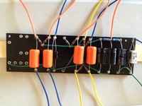
My son and I have been working steadily on the board. We have about 2/3 of the board finished now, with the notable exception of the .02µF orange drop cap (more on that in a bit). So far I'm pretty happy with the soldering we've done, except for one that I think we got too hot, as the 1 Mega-ohm resistor (which correctly measured 1M-ohm before install) now measures considerably higher at 1.48 Mega-ohms... :oops: So we may need to pull that one and get a new one and re-do that whole solder eyelet... What would cause an increase in resistance like this? Is it really possible that I "cooked" the resistor?

Anyway, here's the board as we have it so far:

Attachment:
File comment: Board progress...
IMG_0009_2.jpg
IMG_0009_2.jpg [ 1008.03 KiB | Viewed 21854 times ]


Now, as to the .02µF cap, the reason we haven't wired that up yet is because the cap I have reads 2.22 nF. Now I know my math isn't great, but I'm pretty sure that would be .002µF, not .02µF... I double-read the layouts and the schematic, and it really does appear that it need a .02µF, so unless I'm missing something obvious, I was shipped the wrong cap... The markings on the cap show "SBE 715P 600V" on one line and "222J 0732" on the next line. If I'm reading that right, then the "222J" part means 22*100pF == 2200pF == 2.2nF == .0022µF, which is exactly what I'm reading with the multimeter, so it really does seem like I was shipped the wrong cap. When I went through and took inventory of the kit that was shipped to me against the BOM, I saw .022µF/600V, and saw the "22" and "600V" on the cap, and assumed it was right. I should have measured them all (although everything else other than the switch seems to have been right). I've notified Stephen, and hopefully he'll be patient with me...


Top
 Profile  
 
PostPosted: Sat Jan 25, 2014 7:30 pm 
Offline
Friend
Friend

Joined: Wed Dec 25, 2013 9:15 am
Posts: 14
Location: Santa Cruz, CA
Oh, and in case it isn't obvious, I read in the docs that some folks choose to wire the flying leads on the face of the board for maintenance purposes, so I elected to do so. I'm not sure if it was the right choice or not, but it's certainly made things clearer for me when tracing components, so as long as there are no obvious downsides, then I think I made the right choice. We'll see.

I've been very careful when soldering components to ensure that the component leads are not touching (or too close to) the flying lead insulation, as my son worried that that might cause melting of the insulation, and subsequent arcing. Good call on his part, and we've made sure that doesn't happen.


Top
 Profile  
 
PostPosted: Sat Jan 25, 2014 7:37 pm 
Offline
Friend
Friend

Joined: Wed Dec 25, 2013 9:15 am
Posts: 14
Location: Santa Cruz, CA
Wow, Stephen just got back to me about the cap, and agrees it's the wrong part, and said he'd ship a new one out. Such customer service! On a Saturday no less! I'm quite impressed, Stephen. When dealing with components, there will always be occasional bad parts, and it's awesome that you're standing behind your product and offering great support. More and more I'm glad I went with Trinity for my first amp kit. Keep up the good work!


Top
 Profile  
 
PostPosted: Sun Jan 26, 2014 12:27 am 
Offline
Holy Ghost
Holy Ghost
User avatar

Joined: Sun Mar 13, 2005 4:10 pm
Posts: 7519
Location: Canada
Thanks. I hope this was isolated to your kit. Shipping the part Monday .

_________________
Stephen
Web: www.trinityamps.com. Facebook: facebook.com/trinityamps. Twitter: @trinityamps


Top
 Profile  
 
PostPosted: Sun Mar 30, 2014 4:02 pm 
Offline
Friend
Friend

Joined: Wed Dec 25, 2013 9:15 am
Posts: 14
Location: Santa Cruz, CA
OK, completed all the soldering on the turret board, installed the board, and soldered all the wires into place, to the tubes, grounds, jacks, etc.

Doesn't look great, I know; I'm a big fan of "service loops", so there's a lot of stray wire hanging out. If this ends up being a problem, I can shorten them, but "for now" I'd rather know that pulling the board to check connections (again) will not be too bad a job.

Attachment:
File comment: Completed all soldering with board installed and ready for testing...
photo.JPG
photo.JPG [ 2.15 MiB | Viewed 21575 times ]


Top
 Profile  
 
PostPosted: Sun Mar 30, 2014 4:14 pm 
Offline
Friend
Friend

Joined: Wed Dec 25, 2013 9:15 am
Posts: 14
Location: Santa Cruz, CA
Unfortunately, at this point I'm a bit lost as to how to proceed...

In the testing section of the build manual, it says to never "operate" the amp without a speaker plugged in, and yet in the very next paragraph, it seems to suggest exactly that, i.e. connect up the rectifier tube and fire it up... Do I have to have a speaker connected to do this, or not? I can't imagine why I would, since the speaker is connected to the output transformer, which is connected to the power tubes, which are not yet installed, but I don't want to have gone to all this work, only to mess up due to slightly confusing docs... So I'm hestiant to fire up this puppy without confirmation that I don't need to hookup the speaker to do the initial voltage tests?

Also, seems to me that the docs could have a handy table to makes it clear what voltages to expect at which pins of which tubes when testing... i.e. "V5 (rectifier) with 5Y3 (or equiv.) pin 6 to chassis ground expect m volts"... Is this data available somewhere?

(Another suggestion for the docs would be a clear section on the purpose of each tube and the correlation to the Vn numbering, i.e. V5 is the rectifier, V3 and V4 are the power tubes, V1 and V2 are the preamp tubes. Being a total newbie to the 5E3 circuit, this wasn't obvious to me, and the docs reference the tubes by name, whereas the schematic and layout are by Vn number...)


Top
 Profile  
 
PostPosted: Sun Mar 30, 2014 5:52 pm 
Offline
Friend
Friend

Joined: Wed Dec 25, 2013 9:15 am
Posts: 14
Location: Santa Cruz, CA
So I decided "screw it", and just proceeded... :-)

1) plugged into A/C, no tubes, flipped on the power and standby
a) no smoke (yay!) :-)
b) measured V5 pin 4 to chassis ground at 369 VAC
c) measured V5 pin 6 to chassis ground at (also) 369 VAC
e) wasn't sure which pins were filament pins, and wasn't sure if I should be measuring across the filament pins, or from each filament to ground, so I (once again) said "screw it", and skipped measuring voltages altogether...
2) installed the rectifier tube (V5) and powered on, nothing nasty yet...
3) installed all the tubes and connected to a speaker, volume knobs to 0, and powered on, still nothing nasty, but also silence...

At this point, I figured I messed something up, as I was expecting some amount of hum or hiss... I pulled up the bright volume a bit, still silence... Kinda more slipping into "uh-oh" territory, but I thought I'd crank it and see, and sure enough, as I got near the upper end of the volume pot travel, I started hearing a hiss... :-D (*vbg*) So...

4) volume off, switched to standby, plugged in a guitar, standby on, and slowly edged up the volume, and... Tone! Sweet, clear-but-crunchy tone! I think it's working!

I played through it a bit, wife and kids cringing all the while at what the neighbors might think, as this sucker is _loud_. It's a bit crunchier than I was expecting, so I may have screwed up something somewhere, but it's a _great_ crunch, so I'm glad I messed up... :-)

Still no smoke, a wee bit of "heated-up electronics" smell, which I'm hoping is normal; certainly not alarming.

Some observations that may be reason for concern somewhere:
a) most of the volume control is between 0 and about 2-3, and it totally levels off after that, without gaining much beyond that, although it seems to get crunchier (in a not-so-good way at that point) towards 7 and up; is this expected?
b) crunchier than I was expecting; still smooth, but with some beautiful overdrive, even at fairly low volumes; again, expected? (I've never played a _real_ (nor even reissue) Deluxe...)
c) there's quite a bit of mechanical rattle from the cab, especially on a low "G" note; sounds like maybe it's coming from the front baffle, so this may require some investigation
d) DAMN THIS THING IS QUIET (noise-wise); I was totally expecting hum and hiss, but am getting none; super-cool!

Steve, awesome job on this kit!

I would suggest that the docs could use some improvement (a lot, actually), for true newbies like me, but the quality of the kit and parts (and design and end-result) are very nice indeed. And given the quality of the docs from the other kits I've seen, yours appear to be far better than most and infinitely better than the "schematics-only" kits, so perhaps the comment about docs should be taken with that in mind...


Top
 Profile  
 
PostPosted: Sun Mar 30, 2014 5:59 pm 
Offline
Friend
Friend

Joined: Wed Dec 25, 2013 9:15 am
Posts: 14
Location: Santa Cruz, CA
Oh, and since "pics or it didn't happen"...

Attachment:
photo.JPG
photo.JPG [ 2.43 MiB | Viewed 21574 times ]


Forgive the Corona Light, it's all I had in the house...

FWIW, upon plugging in, the first lick to come to mind was Alex Lifeson's opening riff for "The Analog Kid", so those were the first notes out of this puppy. Through a tele... I know, not exactly the right right amp or guitar for the song, and I should have picked something more appropriate like "Brown Sugar", but hey, the fingers play what they want to play, and that's what came to mind... :-)


Top
 Profile  
 
PostPosted: Mon Mar 31, 2014 10:50 am 
Offline
Holy Ghost
Holy Ghost
User avatar

Joined: Sun Mar 13, 2005 4:10 pm
Posts: 7519
Location: Canada
robillard...sorry for the late reply. Glad the amp is working for you so let me respond to your questions.

1. Manual - suggestions noted and updted. In the version ofthe manual on file, some of this was already in place but we added your suggestions. Thank you!
2. most of the volume control is between 0 and about 2-3, and it totally levels off after that, without gaining much beyond that, although it seems to get crunchier. This is normal. The stock amp is dirty after 3. We have a mod to clean it up (Try this: remove the 25uf cap across the 1K5 phase inverter cathode resistor). Just pull out one end to try it out.
3. mechanical rattle from the cab. Rattle & Tweed! Batten down the hatches. Tighten all the nuts, bolts and screws up. There is a 4-40 tapped hole in the chassis you can use with a 1/2" 4-40 machine screw to fasten the rear top panel to the chassis to prevent vibrations.

_________________
Stephen
Web: www.trinityamps.com. Facebook: facebook.com/trinityamps. Twitter: @trinityamps


Top
 Profile  
 
PostPosted: Thu Apr 24, 2014 1:01 am 
Offline
Friend
Friend

Joined: Wed Dec 25, 2013 9:15 am
Posts: 14
Location: Santa Cruz, CA
Just a follow-up here: I've been playing with this amp for quite a while, and absolutely love it. Haven't encountered _any_ problems so far, it just rocks, and is loud with signal and quiet with noise. Warm and nicely (but subtly) crunchy when driven, clean when I want it. Really having a blast. I think I've made a few future sales for you by taking it into work, and I know I've annoyed some neighbors, both at work and home... :-) The sound sells the kit, I can tell you that.

The only nit I have for it so far is that there are a couple of hardware=related issues with the cabinet. The first is that one of the chassis mounting screw holes was too "soft" (perhaps drilled too wide? or the wood is just a lot softer on that side?) so the screw for that hole sinks into the hole at the top, really deep actually. I could use a washer to mitigate that, but that would look pretty ugly. The other thing is that the cabinet feet are misaligned, so the cab wobbles on a hardwood floor; I've tried re-seating them all, but there is something just wrong with one of the feet, and it doesn't sit right. Still these are minor issues, and cosmetic. The sound is really fantastic.

So again, thanks for a wonderful product and a great build experience. We enjoyed the process almost as much as the excellent end product.


Top
 Profile  
 
Display posts from previous:  Sort by  
Post new topic Reply to topic  [ 21 posts ]  Go to page 1, 2  Next

All times are UTC - 5 hours [ DST ]


Who is online

Users browsing this forum: No registered users and 20 guests


You cannot post new topics in this forum
You cannot reply to topics in this forum
You cannot edit your posts in this forum
You cannot delete your posts in this forum
You cannot post attachments in this forum

Search for:
Jump to:  
cron
Powered by phpBB® Forum Software © phpBB Group